These checks are unique to HSS (Tube and Pipe) members. For bolt and material checks that are not specific to HSS, see the Bolt & Material Checks topic. For weld information, including weld checks specific to HSS, see the Weld Checks topic.
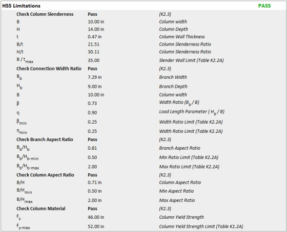
The tables in chapter K of AISC 360 each have a section on "Limits of Applicability". These mean that if a connection falls outside these limits then the procedures given by AISC and Chapter K may not be sufficient to guarantee a safe connection. It does not necessarily mean that the given code checks are invalid. It may mean that the parameters of the connection fall outside the limits of existing test data or that other limit states not listed could control. These parameters are checked as part of the HSS Limitations limit state, which includes checks for:
If any one check fails as part of the HSS Limitations then the entire limit state is considered to fail. When multiple slenderness limitations apply, the most stringent slenderness limitation is used.
Note:
The HSS Beam to Column Moment Connection has specific limitations that must be considered for safe design. These limitations ensure that the connection remains within the scope of available design provisions in the AISC 15th Edition (360-16) and Design Guide 24 (DG 24) – Chapter 9.
Naming Conventions
This connection adapts the same checks used for HSS T‐Connections. “Branch” and “Chord” simply become “Beam” and “Column.”
Design Assumptions
The connection is designed assuming direct weld between the HSS beam and HSS column, without additional stiffening plates.
Geometric Limitations
Design of HSS connections per the Canadian CSA S16 design code refers to the CIDECT Design Guide 3 for Rectangular Hollow Sections and CIDECT Design Guide 1 for Circular Hollow Sections. The CIDECT checks per Table 4.1 and 7.1 are very similar to those in AISC Chapter K and also are limited to parameters outlined in the "Range of Validity" from CIDECT Table 4.1 and 7.1 which includes checks for:
When the HSS member is in compression, HSS Class 1 or 2 is required. The HSS class is defined by CSA S16 Table 2. The HSS member is determined to be in compression when the column axial force is positive for the following connections: Shear Tab, Clip Angle (One Side), and Vertical Diagonal Brace. The chord force is assumed to be in compression for the following connections: Chevron Brace, Knee Brace, and HSS to HSS.
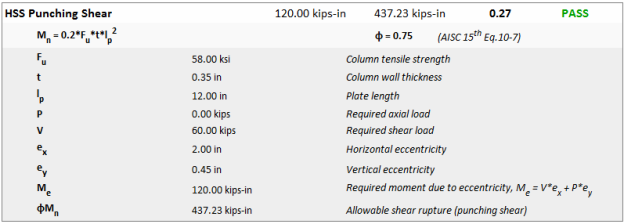
The Punching Shear checks depend on which version of the code you have selected. See the details below.
The punching shear limit for a single plate connection to a HSS tube wall is checked per eqn (10-7) on page 10-153 of the 15th Edition Steel Construction Manual. This is applicable to HSS Tube and Pipe columns with a shear tab connection.
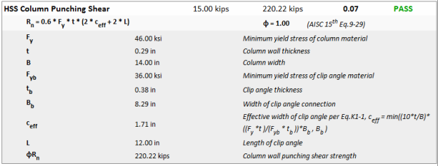
The punching shear limit for a clip angle or end plate connection to a HSS tube wall is checked per eqn (9-29) on page 9-14 of the 15th Edition Steel Construction Manual.
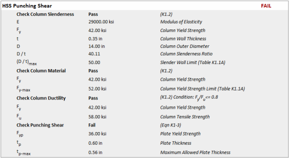
The punching shear limit state for longitudinal plates framing into the sidewall of an HSS member includes the HSS Limitations, as well as a check that the yield strength of the plate does not exceed the rupture capacity of the HSS sidewall.
Note:
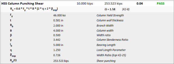
The punching shear check for columns treats the clip angle or end plate as a "branch" tube of equivalent dimensions. This punching limit state is based on shear yielding of the "chord".
Design of HSS connections per the Canadian CSA S16 design code refers to the CIDECT Design Guide 3 for Rectangular Hollow Sections and CIDECT Design Guide 1 for Circular Hollow Sections.
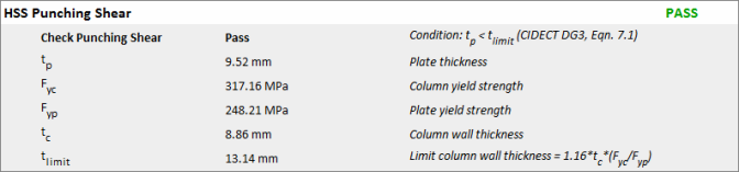
The punching shear limit state for a single plate connection to a HSS tube wall is checked per eqn (7.9) on page 57 for round HSS members and eqn (7.1) on page 75 for rectangular HSS members. These are applicable to HSS Tube and Pipe members with a beam flange (or flange plate) or shear tab connection. The equations in the CIDECT Design Guides check punching shear for shear (longitudinal) plates attached to HSS members by limiting the plate thickness.

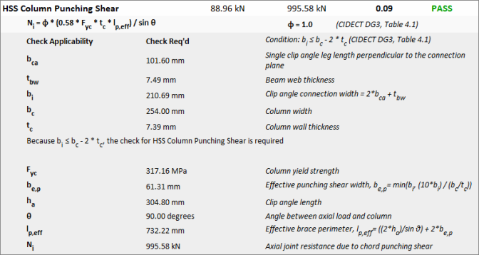
The punching shear limit state for a clip angle connection a HSS tube wall is checked per CIDECT Design Guide 3 Table 4.1 for rectangular HSS members.
See the Welds topic for information on the through-plate weld.
The Transverse Plastification limit for a HSS tube wall is checked per eqn (9-30) on page 9-16 of the 15th Edition Steel Construction Manual.
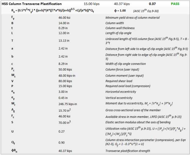
This limit state checks the sidewall for plastification due to axial force in the beam per AISC 360 Chapter K or CIDECT DG 3 Table 7.1.
![]()
Note:
This limit state treats the clip angle or end plate as a "branch" tube of equivalent dimensions. This limit state is based on plastification of the "chord".
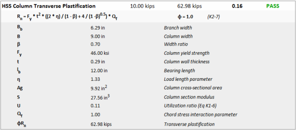
This limit state checks the HSS member face for plastification due to axial force in the beam. For pipe HSS members (CHS) this limit state is checked per CIDECT DG1 Table 7.1, page 55.
![]()
For rectangular HSS members (RHS), this limit state is checked per CIDECT DG3 Table 7.1, page 77.
![]()
Note:
This limit state treats the clip angle as a "branch" tube of equivalent dimensions. This limit state is based on the plastification of the "chord" face per CIDECT DG3 Table 4.1, page 36.
![]()
Note:
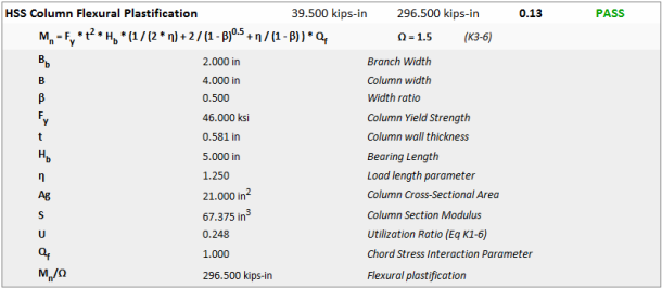
The Flexural Plastification limit for a HSS tube wall is checked per eqn (9-34) on page 9-16 of the 15th Edition Steel Construction Manual.
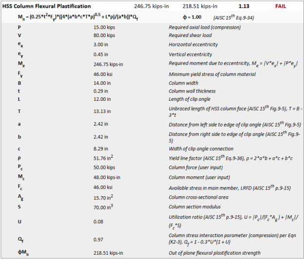
This limit state checks the sidewall for plastification due to bending moment caused by eccentricity in the connection to the beam per AISC 360 Chapter K. This check is only applicable to round HSS (Pipe) columns. It is not included when the column is a rectangular HSS (Tube). Per the AISC 360-16 "Yielding (plastification) of the HSS face has not been a governing limit state in physical tests."
The flexural plastification check for columns treats the clip angle or end plate as a "branch" tube of equivalent dimensions. This limit state is based on plastification of the "chord". The flexure is caused by eccentricity in the connection to the beam.
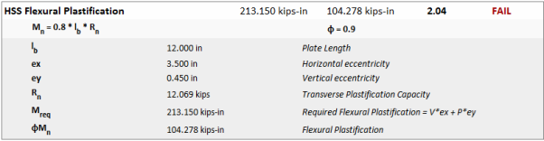
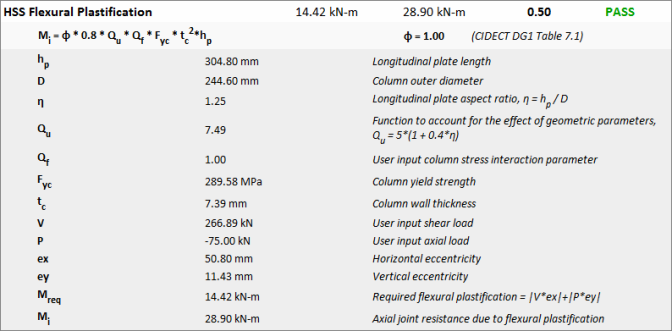
The Flexural Plastification limit state is only required for pipe HSS members and is checked per CIDECT DG1 Table 7.1, page 55. For a column/beam shear tab connection, the required mometn, Mreq, is taken as the same load required by the AISC HSS Flexural Plastification check. For braced connections, this moment is calculated.
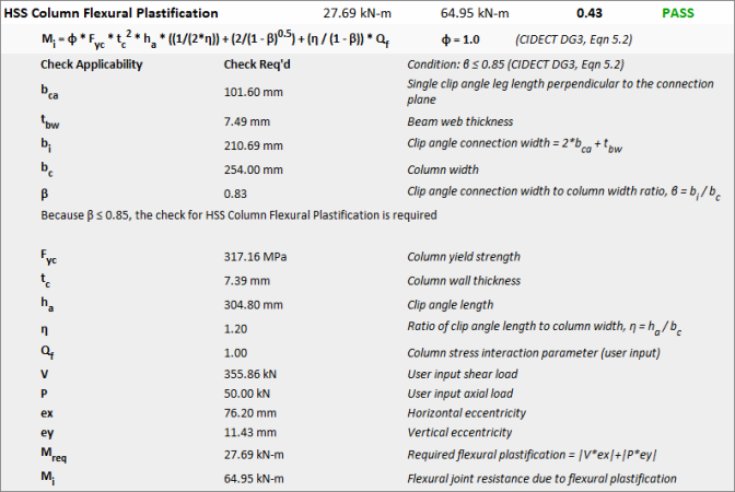
This limit state treats the clip angle as a "branch" tube of equivalent dimensions. This limit state is based on the plastification of the "Chord" face due to in-plane bending per CIDECT DG3 eqn 5.2, page 61. For column/beam clip angle and brace connections, the required moment, Mreq, is taken as the same load required by the AISC HSS Flexural Plastification check. For HSS T-connections, the required moment is the user-input branch moment.
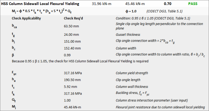
This limit state treats the clip angle as a "branch" tube of equivalent dimensions. This limit state is based on the side wall failure of the "Chord" per CIDECT DG3 Table 4.1, page 36.
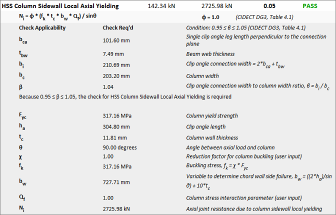
The sidewall local yielding check for columns treats the clip angle or end plate as a "branch" tube of equivalent dimensions. This limit state is based on yielding of the "chord". The flexure is caused by eccentricity in the connection to the beam.
![]()
This limit state treats the clip angle as a "branch" tube of equivalent dimensions. This limit state is based on the side wall failure of the "Chord" due to in-plane bending per CIDECT DG3 eqn 5.1, page 63.
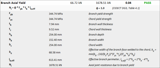
This limit state is based on the local yielding of the branch due to axial load per CIDECT DG3 Table 4.1, page 36.
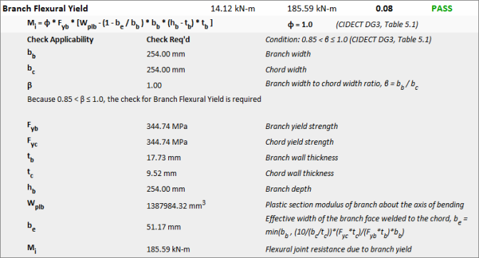
This limit state is based on the local yielding of the branch due to in-plane bending per CIDECT DG3 Table 5.1, page 63.
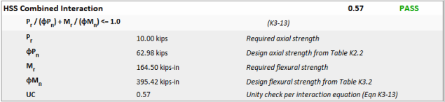
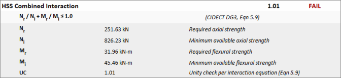
The combination of transverse loads and bending loads on an HSS member is checked to ensure that a combined failure of multiple limit states does not occur at loads that would not fail either limit state by itself. The controlling transverse strength and the controlling flexural strength are used for this check, based on the limit state for each failure mode that has the lowest capacity.
See the Welds topic for information on welds to the face of an HSS member.
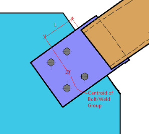
The unbraced length for an HSS brace to gusset connection is defined as the distance from the face of the HSS to the centroid of the fastener group as shown in the image below:
The appropriate unbraced length to use in the compression check for this plate or Tee Stem is a matter of engineering judgment. Therefore, RISAConnection provides an "Effective Length Factor" that can be used to adjust this unbraced length up or down if desired. The default value for this effective length factor is 2.1.
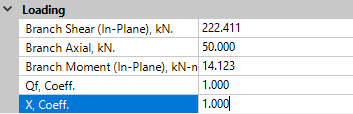
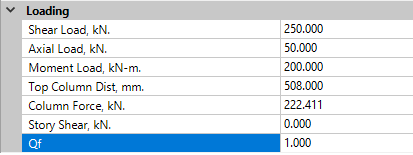
Both the AISC Chapter K Tables and CIDECT DG 3 Table 7.1 include a column stress interaction parameter, Qf. There are some cases where RISAConnection cannot determine this value, so it relies on the user adjusting this in the Loading input properties:
The CIDECT DG3 Table 4.1 includes a column buckling reduction factor, χ, in the HSS Column Sidewall Local Axial Yielding limit state. This is a user input located in the Loading input properties and is used for Clip Angle and HSS T-Connections when the axial load is in compression.